BLOG 4: 3D PRINTING
- wongzl23
- Jul 31, 2024
- 10 min read
Updated: Aug 1, 2024
Hello guys! Welcome back to my LAST blog for my ICPD module!
I have shared with you guys about 3D modelling in my blog 3, and now I am going to write about the physical printing for the design created in fusion! IT SOUNDS SO FUN, RIGHT?
For my final blog entry, I plan to make it XXXTRA special by writing it in the style of a diary.
LETS GET STARTED!!!
20 JULY 2024 (SAT)
I start to work on this assignment practical 5 today. I am tasked to design a print in place artefact with at least one moving joint.
Well, what is the print in place technique?
Print-in-place refers to 3D-printed objects that incorporate various types of joints, moving parts, and hinges that are printed in a single task, which means that the moveable parts of this print-in-place model can be printed as a single piece! These objects are designed to be printed without the need for any further manual assembly, and one can start using the part right away. Print-in-place models can achieve an impressive amount of detail and still maintain a high degree of mobility. The video below offers a visual explanation of the print-in-place technique, complete with the examples.
However, I did not notice that print in place technique is required, and I do research on the 3d design that has movable joint only. Therefore, I am passionate to make a legoman with complicated components as tutorial is available online even though I need to do the design myself. Although I started doing the design which does not fulfill the requirements of this assignment, I have learnt a lot of undiscovered function in fusion 360 which built up my skills on using 3d design software.
These are few parts that I have made for the legoman, hahaha... (head, body and arms)
legoman head
legoman body
22 JULY 2024 (MON)
When I realized that my clumsy vision had caused me to overlook the need for the print-in-place technique, I knew I had made a mistake. 😶
So, I decided to look for a print-in-place hinged box to create instead. However, another mistake occured. 😀 I followed a tutorial video that does not teach on how to do the print in place hinged.....😶This is how it looks like in different components without applying the print in place technique.

BUT!!!
Spending an entire day making a legoman wasn't wasted. I am able to modify the stick to be in the same component with the box that allows all the parts to be printed together. Basically, it just requires extruding the hole on the bottom part of the hinged box, to extend a stick that can join the top part of hinged box together becoming a single object.
This is how it looks like that all components are in the same object to be printed.
It looks very aesthetic like the air Pod case, right? HOWEVER, I decided to abandon my design againnnnn. HAHAHAHAH

Because I realized my hinged part required a lot of support, which was unfavorable for my assignment. If I insisted to do hinged box, I think it is better to be printed with the orientation lying flat on the printer surface like what the below picture has shown, to avoid large amount of support.

23 JULY 2024 (TUE)
Instead of redoing hinged box which a lot of my friends wanted to do this design as well, I searched for other print-in-place 3d object that is more suitable for my assignment. Eventually, I have decided to make a gyroscope which looks extremely interesting to me. Although I am not sure if the design steps in tutorial video will work well on the final printed object as it looks simple, I decided to give it a try. Below is the reference video that I follow for the design.
However, I did not follow the tutorial completely to make it become a keychain because I want it to be no support needed while printing this design which fulfills my assignment requirement. I will continue writing about the steps I took to create the gyroscope design.
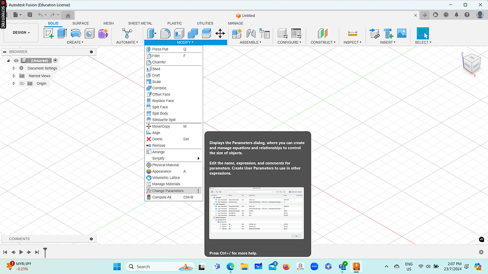
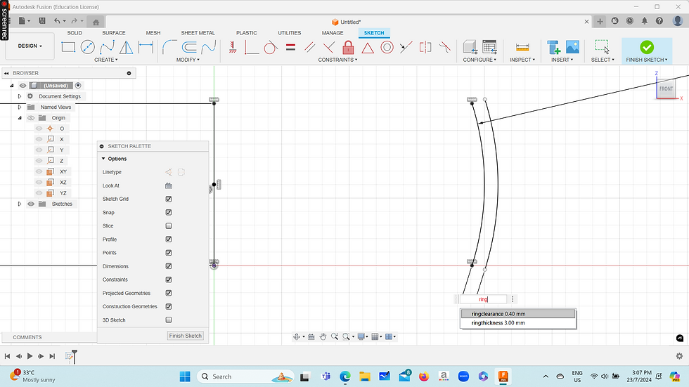
Click modify and change parameter to ensure all the space between every ring is consistent.
2. Set the ring thickness to 3mm.
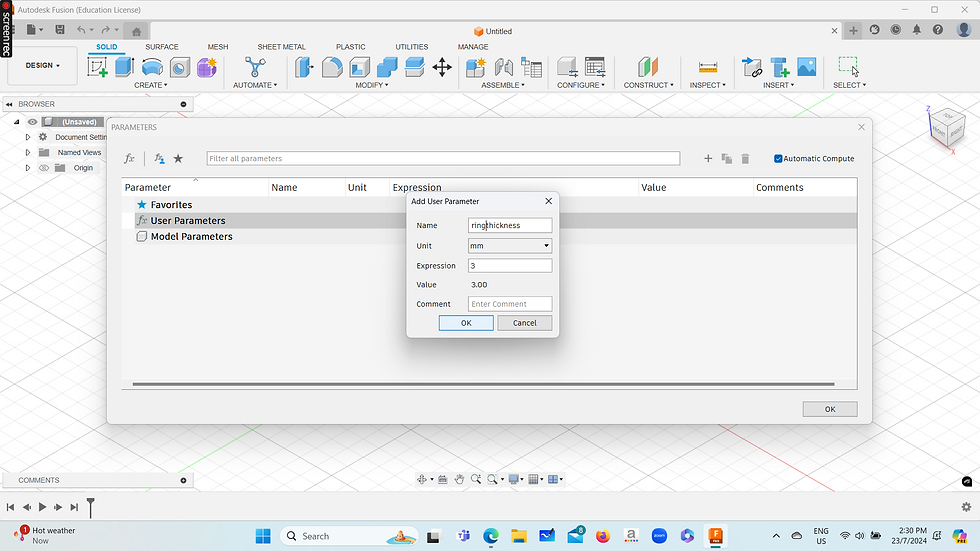
3. Set the ring clearance to 0.4mm.

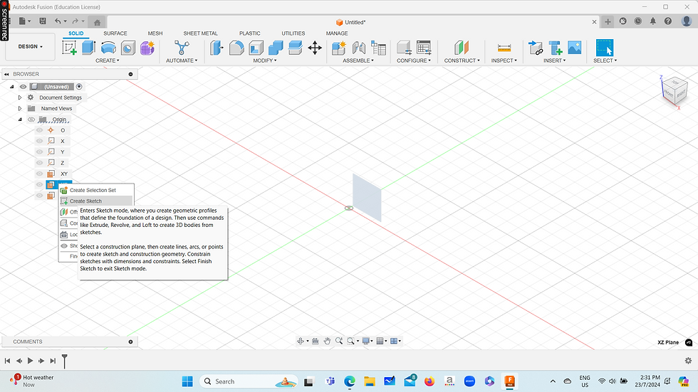
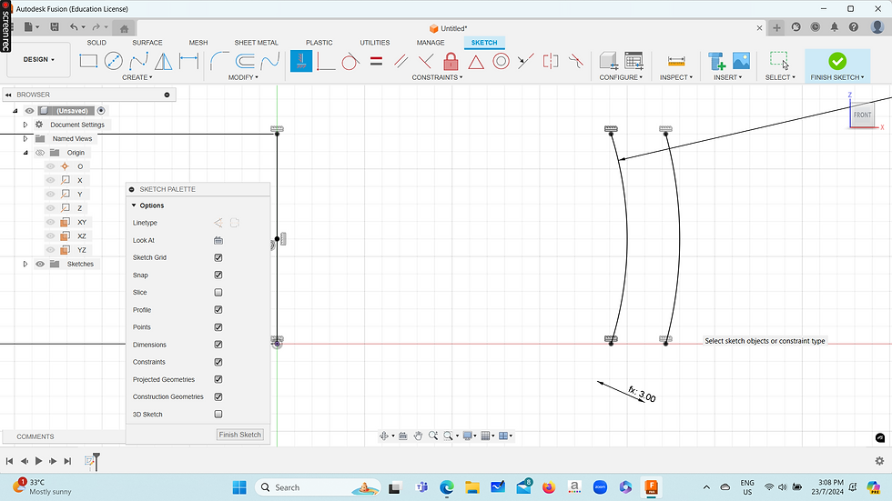
4. Create sketch on XZ plane as we need to revolve the sketch to make it lies flat on the
plane.
5. Create a 12mm line at the middle.

6. Create a 3-point arc somewhere at the right side.
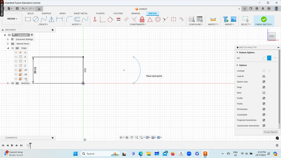
7. Click on MID POINT CONSTRAINT and select the mid point of arc and the mid point of 12mm line.

8. Click on horizontal constraint and select both edge of the arc and line to align the dimension.

9. Select SKETCH and insert a 20 mm diameter for the 3 point arc.

10. Click on OFFSET and select the arc to copy it. Move the copied arc inwards and decide the dimension later.

11. Delete the constraint to define the dimension between the two curves.

12. Add the dimension as RING THICKNESS, which is the 3mm parameter that we set at the first step.
13. Add the horizontal constraint again on both of the curves to align them.
14. Sketch lines to close the top and bottom gap of both arcs. The first ring is done!

15. Repeat the steps by offset the inside arc.

16. Delete the constraint again to define its dimension.

17. At this point, dimension selected in between these 2 arcs is the RING CLEARANCE 0.4mm.
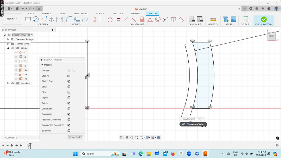
18. Align the top and bottom of arc with the horizontal constraint tool again.

19. Repeat step 10 to 18 for 3 times. You will get a shape as shown below.

20. Add a line on the last curve to close the shape.

21. Here comes the magical part! By revolving the sketch around its axis, it transform into a gyroscope.

22. This is how our final design looks like!

24 JULY 2024 (WED)
After completing the design, it is time to test it out with 3d printing!
Today is the day which I am having my practical session at W3. There is few 3d printers in my school lab. I try to print my gyroscope design after class, and this is my first time using a 3d printer.
Below is a random rooster I came across while walking to the printing lab hehe.

I will record down the steps to use Ulti maker 3d printer in my lab although it is easier than I expected.
Write our name, class, admission number and time we start to use the 3d printer, onto a log sheet.
2. Take the pen drive to save our file design.

3. Insert the pen drive into the 3d printer and select the correct file name for printing.

4. The printer will preheat the nozzle and build the plate. Then, it will process print file by itself! All you have to do is just wait for the printed object to be completed.
5. This is how my final printed gyroscope looks like. Overall it is acceptable but the joint aren't smooth.
Eating kaya butter toast🍞 + half boiled egg🥚+korean ramen🍜 at food court 1 after I have done with my 3d printing. 🫦🫦🫦


"A well-fed person can think more clearly, work more effectively, and enjoy life more fully."
-------- Unknown
29 JULY 2024 (MON)
The sky at 7am, painted with early morning colours.
早八人 leaving home for school. 😭

Obviously, I was not satisfied with the printed gyroscope version 1. Therefore, I decided to try printing it again in the T1442 printing lab.
*TO ALL MY SP FRIENDS WHO ARE READING MY BLOG, DO NOT FORGET TO WEAR LONG PANTS WHEN ENTERING THE PRINTING LAB!
Since the flow of printing is about the same with what I have introduce in the previous part, I will dive into the therapeutic printing video of my gyroscope directly.
My version 2 gyroscope is printingggg.
So the 3d printer I am using in this lab is the Bambu Lab brand. It also has faster printing time than the Ultimake printer. It only took 26mins to complete printing the original size of my gyroscope whereas to achieve the same printing time with printing using Ultimaker printer, I have to scale the object down becoming 75%.

Unexpectedly, the quality of printing in this lab is way better than the printer in my practical lab with the same STL file! The joint is smoooooooooth. YES FINALLY.
And what's even more surprising is that I found out from my lecturer that the better printer (Bambu Lab) is significantly cheaper than the ULTIMAKER printer.......
HAHA, anyway this is my final printed gyroscope model looks like.
It is extremely smooth but my demonstration abit cacat.😀


Trying out KFC's newly launched ondeh-ondeh egg tart and michelin popiah at Clementi after printing.😻


31 JULY 2024(WED)
It is my practical test today and I am back to W3 lab. Submitted my printed gyroscope.

Eaten a mentaki salmon bowl and sambal petai prawn for lunch today.


1 AUGUST 2024(THU)
Today doing the write up for my practical 5 submission~~~
Firstly, I have to explain why my design cannot be easily manufactured by subtractive technology.
So, what is subtractive technology?
Subtractive technology, or subtractive manufacturing, is a process where material is removed from a solid block, or workpiece, to create a desired shape, contrasting with additive manufacturing (i.e. 3d printing) where material is added layer by layer. Subtractive manufacturing by manually cutting the material is also possible. In fact, before the Industrial Revolution, that was how most of it was done. This traditional form of manufacturing has evolved over centuries from simple handcrafting to sophisticated CNC machinery, reflecting the technological growth of society. A milling machine cutting/hollowing out a piece of metal or plastic is an example of subtractive manufacturing.

In this image, the machine is gradually removing bits from the block. This is an example of subtractive manufacturing.
-----------
Gyroscope cannot be easily manufactured by subtractive technology. These are the reasons:

Actual gyroscope image
1. Complexity of gyroscope’s geometry
Subtractive technology is removing part of the material from a round solid to create the shape of gyroscope of with different sizes of ring. As you can see from the above pictures, the actual gyroscope has spin axis and pin to allow different parts to rotate on their respective directions. Therefore, using traditional subtractive technology, the gyroscope frame, gimbal and rotor need to be produced separately in a single piece and assembled them together with the pins. Due to the reason that the geometry of gyroscope is complex, the assembly will require high accuracy of measurement and alignment on every single part of the gyroscope. If there is error in dimension, this gyroscope model might not be able to move smoothly. Therefore, by using the additive manufacturing, which is our 3d printing to build the gyroscope, it is much more convenient. Using the print in place technique, the gyroscope is printed layer by layer with appropriate ring thickness and ring clearance. Then, the printed object can be rotate and move without assembling process.
2. Time consuming
By using subtractive technology, it involves multiple steps from producing the round shape of gyroscope, removing additional part in this round object to create ring clearance and assembling the pins together with every rings. Thus, it requires more manpower, tools and machines to complete the gyroscope. Every process needs to be highly precise and consistent on the measurement of dimension of every part of the gyroscope especially the removal of the ring clearance. As these processes can be slow due to the complexity, more time is required as it goes through complicated processes.
3. Waste of material
As nowadays the world is working towards sustainability, producing the object by subtractive technology could be hard due to environmental concerns. By creating a round solid object and removing the excessive ring clearance part to build a gyroscope will produce waste of materials. Higher cost will also be needed due to more materials required. Therefore, it is hard to use subtractive technology in producing the gyroscope as it is economically and environmentally undesirable.
4. Fragility of material
By using subtractive technology, it is easily break and crack while adding force to cut away the unwanted parts of ring clearance due to the hardness of material. Therefore, instead of using subtractive technology, an additive technology could be an easier operated choice as the ring of gyroscope is built from melted filament according to the desired ring thickness, so it does not require to remove excessive ring clearance from a solid material.
Then, I also wrote about the slicer setting and print quality of my 3d-printed gyroscope.

Print setting of gyroscope in Cura preview model
1. The orientation of my design is as photo shown above. The best thing about this gyroscope design is that there is no any support needed as it lies flat on the 3d printer while printing. Hence there is also no rough edges required to touch up after printing.
2. No adhesion needed as well because it is easy to take off from the 3d printer after printing. Thus, disabling the adhesion will result a skirt around the gyroscope by default.
3. As this gyroscope printing is for demonstration purpose, infill selected is 10% to save printing time and filament material. This infill pattern triangle is chosen because it is strong and enough to support the strength of my tiny gyroscope. These setting reduce the weight of my printed gyroscope as well as its printing time. By choosing these infill setting, it is proved that the printed gyroscope that I have submitted does not break easily.
4. Fast resolution 0.2mm is chosen because it does not require fine printing for my gyroscope.
5. Although the estimated printing time is 49 minutes with 12g of my object (original size) on Cura app, I used the Bambu Lab 3d printer instead to print my design that has a faster printing time and better printing quality. As shown as the photo attached below the printing time for my gyroscope design is only 26 minutes with a 10.9g. Therefore, it does not exceed the required printing time which is 1 hour.
6. In terms of joint smoothness, the printed gyroscope that I have submitted shown that it is perfectly smooth for every ring and their direction.
Hence, after looking through a lot of tutorials online, I have chosen to do this gyroscope design as this is perfectly fit for this assignment that fulfils the requirements that is print-in-place technique and cannot be easily manufactured by subtractive technology. Moreover, all the joints are smooth, short printing time, no support and adhesion needed as well as no post printing touch-up required.
Last but not least, the is the fusion file for my final design object that I have submitted.


Comments