#BLOG 3: Design for 3D printing
- wongzl23
- Jul 7, 2024
- 8 min read
Updated: Jul 19, 2024
We have finally reached the interesting part of this module, which is 3D printing!
So, what is 3D printing?
3D printing is the construction of a three-dimensional object from a digital 3D model. It is part of an additive manufacturing process where an object is created by adding material layer by layer. The 3D model is designed and created using modelling software like Microsoft Autodesk Fusion 360 or the readily available model design by other users can be downloaded via website such as Thingverse.
Autodesk Fusion 360


Thingverse
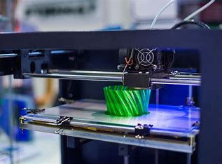
While there are many types of 3D printing, the Fused Deposition Modeling (FDM) and the Stereolithography (SLA) are most commonly available to hobbyists and makers due to their relatively lower cost. I will specifically talk about the FDM as I will be using this type of 3D printers in my school lab! The FDM 3D print uses thermoplastic polymer in filament form to create the final physical object. You may wonder how this works. The thermoplastic will be fed into a heated nozzle, then the filament will melt and precisely deposit layer by layer onto the build platform according to the digital model created.
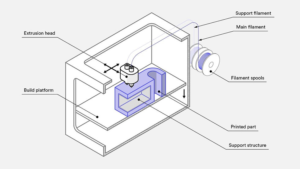
Below is a schematic of a typical FDM printer to provide you a better understanding to visualise how does it works.
Imagine being able to create any invention that comes up in your mind or innovate any brilliant ideas making a tool even more functional, and then watch it materialize right before your eyes! Explore these endless possibilities with me, we will learn not only the technical skills required to operate the 3D printing machine, but also the creative thinking process of how to design a 3D model!
Watch this video below and look at how these two 3D-printed models seamlessly fit together in any way they are inserted into each other!
Also, watching how they design, print and assemble all the parts of this dancing skeleton is kind of therapeutic!!!
Chuck Hull: The Pioneering Inventor Behind Stereolithography and 3D Printing

Have you ever wondered about the genius behind 3D printing? Well, let me introduce you to Chuck Hull, the visionary inventor who revolutionized the print industry. In the early 1980s, Hull’s invention of stereolithography, also known as 3D printing, changed the game. By printing layer upon layer of plastic, he made it possible to create three-dimensional objects like never before.
Stereolithography utilizes a process of printing thin layers of ultraviolet curable materials to create objects. This technology quickly gained popularity and was widely used in rapid prototyping and direct manufacturing. Industries such as car manufacturing, aerospace, and medical printing began utilizing Hull’s systems for building prototypes and producing various components.
Sharing on my learning in 3D printing design
After looking at some fun facts and working principle of 3D printing, I want to share about my 3D printing learning with you! I was first introduced this fusion software by my lecturer through the keychain design. Below is the customized keychain that I have made after learning from this lesson. It was pretty easy because I just need to follow the instruction given by my lecturer. However, the bigger challenges are ahead....

After that, the next lesson, me and my teammates have to design a PHOTO FRAME for our group assessment, which is our CA1. Each of us designed each part of the photoframe, and this is how the final design looks like.
A sharing on my practical assessment

Then, I was tasked to design a motor casing for windmill. Photo shown at the right is the DC motor that need to be fit in my motor casing.
For me, the most important thing in designing a product is to create solution, do the LEAST amount of design to solve SUBSTANTIAL problems so I decided to keep my design simple and useful. Let us take a look at how I design the casing to house this DC motor.
Being a complete beginner on this 3D print design, I have no prior knowledge on how to use this software. Therefore, simply relying on what the teacher has taught is obviously not enough. Before I start to think about my design for the casing, I searched online for a lot of tutorials on how to use this software, most of them are from YouTube. I believe that learning through videos is a great way to study because we get to visualize the points we need to learn, which helps enhance our understanding more effectively. Some of the skills that I have learnt are hollow a 3D object created, extrude an object with different surface on both side of the object, use the pipe tool to create different shape of pipes by simply just drawing lines!
These are few of my considerations before starting my design in Fusion 360 software:
size of motor
wire location
shape of motor
thickness of casing wall


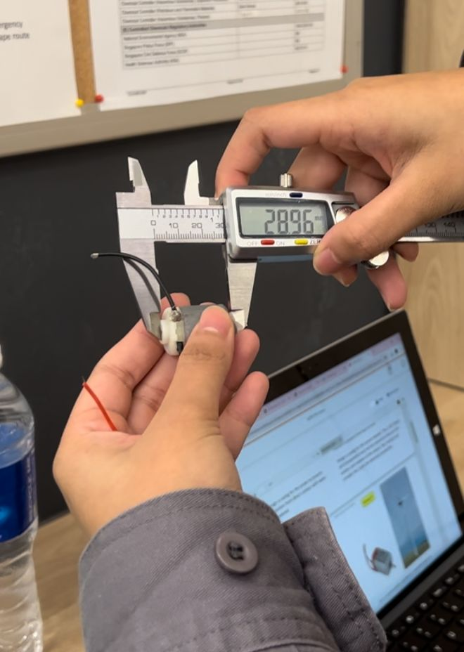

I have taken down the measurement of the motor required my casing design and sketch an initial design of the casing size and shape that can fit in the motor.

Tutorial on designing my motor casing
Watch this video below and follow my steps on fusion 360 if you want to make a same casing for your motor as well!
Written steps on how I design my motor casing in Fusion 360 software:
A. Base shape of motor casing
Click on top view and sketch.
Select line on the top left corner. Drag the line from origin till 16mm. Double click to end the line.

3. Click create. Select 3-point arc to create the curve side.
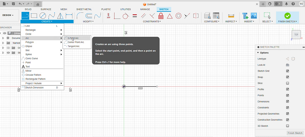
4. Click from origin to 16mm. Drag the curve from center to 3mm away.
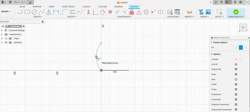
5. Repeat step 2 to 4 and you will get the shape of casing. Click finish sketch on the bottom right corner box.
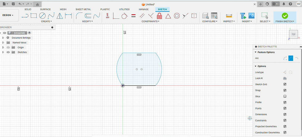
6. Select the shape and click extrude 30mm. The operation is new body.

7. The base will become a 3D model!

B. Space for wires
8. Click front view and sketch. Put a 16mm x 4mm rectangle at the bottom part of front view.

9. Click finish sketch. Select the sketched rectangle and click extrude 2mm. The operation is join.

9. Click the rectangular part and click shell on the 3rd button under modify.

10. Define thickness for 0.8mm. Both sides will be hollowed together!

C. Part for the end cap of motor
11. Click the bottom view and sketch. Select circle and place at center point of bottom view.

12. Define diameter as 10mm and click finish sketch.

13. Click on the sketch circle and click extrude -0.8mm. The operation will be cut.

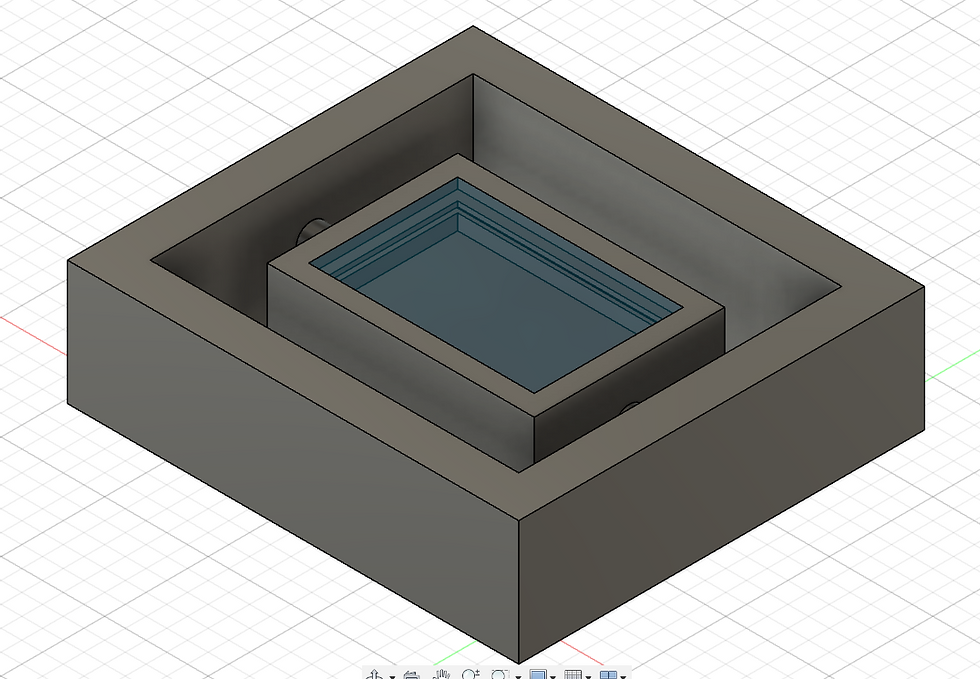
14. Finally, the space for end cap is ready! This is how the final model looks like.


I was confused by the extrude operation when I was doing this assignment. As long as you understand the basic concept of the functions, you will be able to create whatever shape in your mind!
An overview of my motor casing design
The rectangle space extruded is the space for wire to pass through. Moreover, the hollow part on the top is to insert the motor in the casing. You will notice that there is also a hole at the bottom part of my design because the motor has an extra circular part on it. The thickness of casing wall chosen is 0.8mm because this is the typical minimum thickness that required for 3d printing, and the motor is small so I do not need extra thickness to support it. It will save the printing time and cost of material to print and build my design.
Next, it's time to convert my finished design into this Cura preview model to be ready for printing!

Let us take a look on the workflow in 3D printing to understand why this step is important.
WORKFLOW IN 3D PRINTING
1. Creating a printable 3D Design in Fusion 360.
2. Converting the 3D design into a 3D representable file in STL or 3MF format.
3. Slicing the 3D representable file (STL or 3MF) into layers using Cura slicer software.
4. Converting the layers into instructions for the 3D printer (gcode).
5. The 3D printer creates the 3D object.
How to convert your fusion design into Cura preview model?
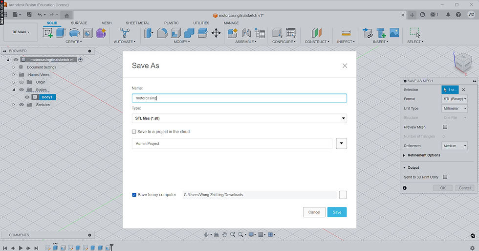
First, in fusion 360 software, right click body and save as mesh.

2. A box will pop up on the right. Ensure it is STL file and click OK.

3. Rename your file and save it.
4. Download and open Ultimaker Cura. (This is the most troublesome step for me when I first time convert my design into Cura Preview Model. I don't know why it keeps asking me to set up a printer and I cannot click anything to skip this step. Eventually I found a local printer button and chose it. And I am finally done with setting up this app!)
5. Open your fusion file in Cura.

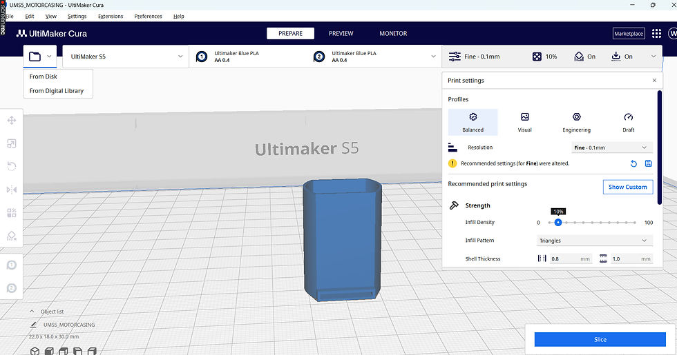
6. Your fusion design model will show on the screen. Adjust your setting at this top right corner box.
7. Click slice at the top right corner. You will be able to see the printing time of your model.
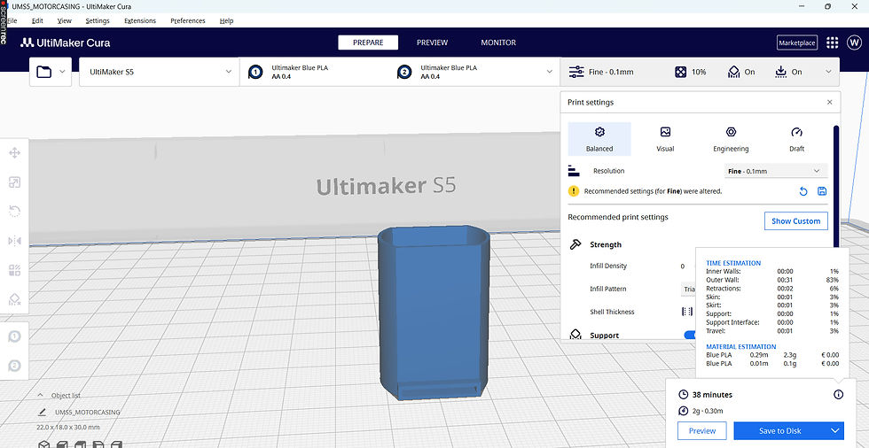
7. Click the preview. And you have finally converted your design into Cura preview model.

Printing instruction of my motor casing
At this point, you can decide the print setting based on the consideration between printing time and quality.
For resolution, I chose 'fine' which is 0.1 mm because my casing is very tiny and does not require long printing time. Therefore, I have chosen a finer print to give a better quality of my motor casing product.

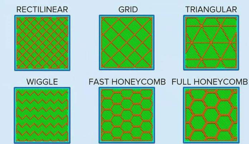
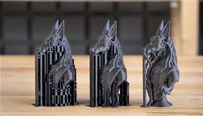
Second, strength. Infill density, infill pattern and shell thickness define the strength of your part. I chose the typical minimum wall thickness which is 0.8mm because it has enough strength to support my casing whereas the infill pattern of triangle is automated chosen by Cura app. Below are some of the infill patterns for structure works.
I have chosen 10% infill density the main reason is because heat loss to the surrounding will be faster as when the motor is running, it will heat up the casing as well. Also, 10% is a typical infill density choice and it is sufficient to support my small motor casing. Another reason is that printing time needed is lesser if I choose a relatively low infill density. AHHH, SUSTAINABILITY?? YES! It saves material to print it as well. Plus I want it to be as light as possible so that 10% of infill density must be the best choice for me! Btw, you can refer the photo below for better understanding of model with different infill density.

Third, support. Supports are used to aid in printing overhangs as the model cannot be printed in 'air'. The supports are removable from the model after printing is done.
Starting with the best orientation to minimize support needed, the face with a 10mm diameter hole is chosen as my bottom base for printing.

As you can see, the only parts that required support in my design is the space for wire.
Why didn't I consider making it as 2 circle holes instead of one hollowed rectangle on the casing?

Because I feel that it is not easy to install the motor into the casing because it is super small. If I insert the motor for the top of my casing, it is unlikely that my hands are able to pull out the wires from 2 tiny holes.
Therefore, a rectangular space is a more reasonable design due to its size concern. Although support is needed for this design, I still think the functionality outweigh its longer printing time, isn't it?
Fourth, adhesion. Below is typical type of bed adhesion chosen to provide stability for the model. I have chosen brim as my adhesion for the motor casing to allow some printing parameter.

Since we are not tasked to print the design of this motor casing, I will stop my typing here. This is all about the short introduction of the motor casing that I have designed. Hope you guys will start to create your design in 3D model as well after reading my blog!
Stay tune for my next blog as I will be sharing more about another design that has moving joint. It will be a more interesting blog than this as I am going to print my design rather than just sharing all the skills to use fusion software. And I have not used a 3D printer before, most likely I will be facing a lot of obstacles while doing my next practical. I will share all my experience and things to take note so that you guys are also learning along with me while reading my blog! Thank you for spending your precious time reading my blogggggg.
Have a nice and pleasant day~~~

Comments